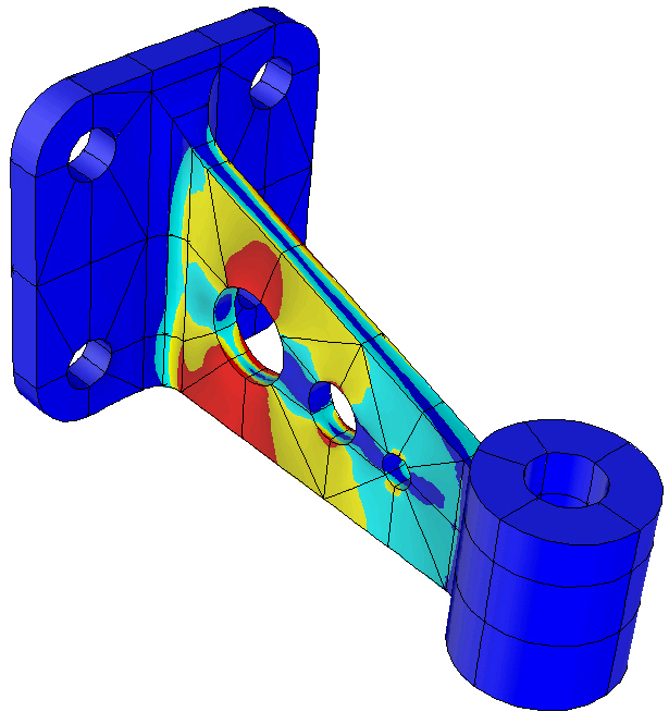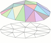
The type of algorithms I analyze are based on the so-called Finite Element Method , where the component being designed is broken up into regular-shaped pieces (on the computer, for the purposes of calculation) as seen in the picture of the bracket above. To understand this better, let us consider a simpler example, that of a circular membrane (say a piece of a balloon). Suppose this balloon skin is stretched into a flat circular shape – this is its resting state. Then suppose this skin is subjected to a force (say a powerful wind) which deforms it, say into a spherical cap (just like the top of a balloon when you blow it up). One could set up a mathematical problem, which would take into account the wind acting on the balloon, and the fact that initially it was clamped into a flat circular shape. If one could solve the resulting equations exactly, then the solution would give the deformation of the balloon, which would be precisely the spherical cap shape. However, the equations are quite difficult to solve exactly. What the finite element method does, essentially, is to replace the balloon skin by a number of triangular pieces (the “finite elements”). Instead of thinking of the balloon as a completely smooth and pliant surface, we now think of it as made up of these facets, which can stretch and rise and expand, but must always remain flat triangles (see illustration below). This significantly reduces the complexity of the problem – whereas before the balloon surface had complete freedom to deform in any way, it is now much more constrained, since the flat triangles must always remain flat and triangular. Looking carefully at the picture below, one notices that the deformation of the balloon is now entirely determined by the final positions of the vertices of the triangles. Essentially, the problem has been reduced from one where we had to find the final position of each and every point in the balloon (an infinite number) to one where we only need to find the final positions of the nodes of the triangulation (a finite number). The new, simplified problem can be solved on a computer.

Of course, the downside is that we can never get a perfectly smooth and spherical cap as our solution now. We will only get an approximation, as seen in the top part of the figure above. Of course, we could improve our solution by taking more triangles – i.e. dividing the surface up into an initial triangulation that is more fine. Under certain conditions, one can prove that as one takes more triangles, the approximate solution gets closer to the exact solution (in fact, one can even bound the error between the two).
Research problems in finite elements.
Current research in finite elements focuses on several areas, such as improving techniques to estimate the error made in these approximations, or designing new elements suited to the increasingly complex and varied problems that arise in science, industry and business each year. For instance, some of my work has been on the so-called ‘p’ version of the finite element method, where the number of pieces (elements) is kept fixed, but the number of ways in which each piece can deform is steadily allowed to increase (for instance, by no longer requiring that the initial triangles remain flat or triangular). This technique can actually yield better accuracy than the traditional version for some important engineering problems. The stress distribution in the bracket shown on the top was computed using the p version code Stress Check.
Some of my theoretical results have been used in commercial programs such as MSC.Nastran and Stress Check. For example, one of these has been the analysis of a buckling algorithm implemented in Stress Check, where the characterization of spurious values that could creep into the calculations was performed.
![[Stresses in bracket]](http://manilsuri.umbc.edu/wp-content/uploads/sites/261/2015/02/zok.jpg)
As another example, let me mention the collaboration with Professor Panos Charalambides and Dr. Haan Seung-Ill of the Mechanical Engineering department at UMBC on the computational analysis of woven composite materials . These are materials made of fibers woven together and embedded in a matrix (or surrounding material), a process which allows the combination of different components that can contribute different advantageous characteristics to the composite. The picture above shows a sample of such a material provided by Zok, McNulty and Steyer. Here, the matrix is a ceramic one, and one can make out large pores or voids between the fibers. The problem is that due to the various layers and materials used, the numerical simulation of these composites is now very complicated. The problem of dividing such materials into finite elements is quite a challenge, because if the elements get too small, then they might only cover one part of the material, and not be representative of the whole composite. The solution we came up with was to design a ‘p’ version type finite element method which remains large enough to incorporate all aspects of the material (with accuracy being achieved by allowing more and more varied deformations within each element).
Let me remark that the application of finite elements is not restricted to the above areas, but rather extends to fields as diverse as hydrodynamics and dentistry.